Cabling Your Network
- Coaxial Ethernet
Coaxial ethernet is really a fading concept. Two types are available, Thick-wire and Thin-wire. Thick-wire is very unlikely to be found on modern networking equipment but thin-wire is fairly common. Thin-wire ethernet consists of lengths of 50ohm coax cable that are terminated in BNC bayonet connectors. Thin-wire compatible equipment sport a round barrel that the coax is plugged into. Unfortunately, connecting thin-wire is not always so simple. It is important that a thin-wire cable is correctly terminated and not all thin-net NICs are able to automatically terminate a cable. In this case, it is necessary to use a t-piece c/w a terminator so that a cable impedance of 50ohm is maintained. Failure to observe this will result in communication problems between the network devices.
Note: Thin-wire ethernet is also known by it's technical notation of 10base2.
- TP Ethernet
TP, or Twisted Pair Ethernet is the modern equivalent of 10base2 cable systems. Far more flexible, neater and less prone to network faults, TP appears on a myriad of networking and communications equipment. If you have your single PC already connected to your CM then you are already using RJ45 TP cabling and it will almost probably feature in your network. CAT5 cable consists of 4 pairs of wires, with each pair being two insulated copper wires twisted together. These 'twisted-pairs' are then sheathed in a plastic outer sleeve that come in a variety of colours, although 'computer' beige is probably the most common;-). The standards for ethernet over Cat5 cabling define a maximum length of 100 metres for operation at 10MBps, but in practice it is perfectly possible to extend this maximum by 20 or 30 metres without detriment to network communication.
RJ45 refers to the connector that is crimped onto the end of the CAT 5 cable. The connector is rectangular in shape and has a tab at the top. The cable is inserted so that the tab latches onto a small recess in the socket, rather like the side latch on the ubiquitos BT telephone plug.
Connecting a Single PC to a CM connected PC
- With Thinwire

For this set-up a single piece of thinwire co-ax is used to connect two PCs, with each end of the cable physically connected to a T-piece, with the 'spare' connector capped with a terminator to maintain the cable impedance.
It is important to use the correct cable type for thinwire so that the impedance is correct. The official designation is RG58.
- With RJ45

Where two PCs are connected using an RJ45 cable, a cross-over cable needs to be used. An RJ45 cross-over cable actually crosses the transmit and receive pairs in the cable so that one NICs transmit connects to the other NICs receive, and vice versa.
Connecting Multiple PCs to a CM connected PC
- With Thinwire

To add additional clients to the network, remove one of the t-pieces and connect another thinwire coax cable to the vacant connector and replace the terminator at the t-piece of the last device.
Note that some network cards have an on-board termination setting.
- With RJ45

In an RJ45 cabled network, adding additonal clients requires the use of an intermediary device such as a hub or a switch. PCs connect to the hub/switch using straight cables and these are, in turn, connected internally within the hub or switch.
In this environment, there is no requirement for RJ45 cross-over cables.
Straight v. X-over Cables
The requirement for RJ45 cross-over, or x-over, cables is dictated by the type of devices that are being connected. There are two interface types associated with networking equipment, DTE (Data Terminating Equipment) and DCE (Data Communications Equipment). DTE devices mainly consist of PC NICs and Routers. When connecting a DTE device to a DCE device, e.g., a PC to a Hub, a straight cable is required. When the two connecting devices have the same interface type, i.e., both DCE or both DTE, then a x-over cable is necessary.
Device I/F Type Device I/F Type Cable Type PC DTE Hub Port DCE Straight PC DTE Cable Modem DCE Straight PC DTE PC DTE X-Over Hub Port DCE Hub Port DCE X-over Unfortunately, these examples do not constitute hard and fast rules. Some Cable Modems, especially those integrated in Set-Top Boxes, have DTE interfaces, so any PC or Router that connects to it will need a x-over cable. Also, when connecting two hubs together a x-over cable may not be necessary if one of the hubs has an uplink port. An uplink port will have a DTE type interface, so a straight cable can be used to connect to another DCE port, such as a hub port. On many hubs, one of the ports may have a port that is switchable between DCE and DTE. This function can be manual, so a switch has to be activated, or an interface can auto-detect what type of interface it needs to be.
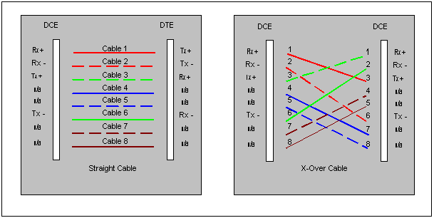
The following diagram shows the necessary cabling required for both straight and x-over CAT5 cables. Each of the four pairs in a cable are colour coded for easy identification, although the colours may vary between different cables.

The Tx and Rx refer to Transmit and Receive respectively, with the + and - symbols refering to the polarity of the signals. A DTE device will transmit data using cables 1 and 2, whilst a DCE device will transmit on Pins 3 and 6. The transmit cables at one end must be connected to the receive cables at the other end for the connection to work. When constructing cables, it is important that the polarities are maintained so that the cable is not affected by interference.
All Copyrights and Trademarks ACK'd. Not to do so would be a SYN!